Custom Search
GAS POWER CYCLES
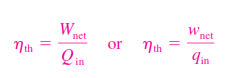
Heat engines are designed for the purpose of converting thermal energy to work, and their performance is expressed in terms of the thermal efficiency , which is the ratio of the net work produced by the engine to the total heat input:
The ideal cycles are internally reversible, but, unlike the Carnot cycle, they are not necessarily externally reversible. That is, they may involve irreversibilities external to the system such as heat transfer through a finite temperature difference. Therefore, the thermal efficiency of an ideal cycle, in general, is less than that of a totally reversible cycle operating between the same temperature limits. However, it is still considerably higher than the thermal efficiency of an actual cycle because of the idealizations utilized
The idealizations and simplifications commonly employed in the analysis of power cycles can be summarized as follows:
1. The cycle does not involve any friction. Therefore, the working fluid does not experience any pressure drop as it flows in pipes or devices such as heat exchangers.
2. All expansion and compression processes take place in a quasi equilibrium manner.
3. The pipes connecting the various components of a system are well insulated, and heat transfer through them is negligible.
Thus the work done can be graphically expressed as:
CARNOT CYCLE & ITS VALUE IN ENGINEERING
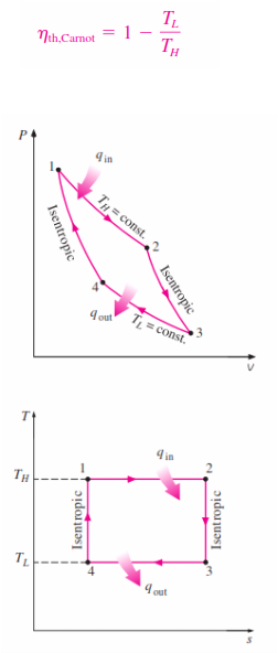
The Carnot cycle is composed of four totally reversible processes: isothermal heat addition,
isentropic expansion, isothermal heat rejection, and isentropic compression. The Carnot cycle can be executed in a closed system (a piston–cylinder device) or a steady-flow system (utilizing two turbines and two compressors), and either a gas or a vapor can be utilized as the working fluid. The Carnot cycle is the most efficient cycle that can be executed between a heat source at temperature and a sink at temperature , and its thermal efficiency is expressed as
The P-V and T-S diagram of the Carnot Cycle is shown :
Reversible isothermal heat transfer is very difficult to achieve in reality because it would require very large heat exchangers and it would take a very long time (a power cycle in a typical engine is completed in a fraction of a
second). Therefore, it is not practical to build an engine that would operate on a cycle that closely approximates the Carnot cycle.The real value of the Carnot cycle comes from its being a standard against which the actual or the ideal cycles can be compared. The thermal efficiency of the Carnot cycle is a function of the sink and source temperatures
only, and the thermal efficiency relation for the Carnot cycle conveys an important message that is equally applicable to both ideal and actual cycles: Thermal efficiency increases with an increase in the average temperature at which heat is supplied to the system or with a decrease in the average temperature at which heat is rejected from the system. The source and sink temperatures that can be used in practice are not without limits, however. The highest temperature in the cycle is limited by the maximum temperature that the components of the heat engine, such as the piston or the turbine blades, can withstand. The lowest temperature is limited by the temperature of the cooling medium utilized in the cycle such as a lake, a river, or the atmospheric air.
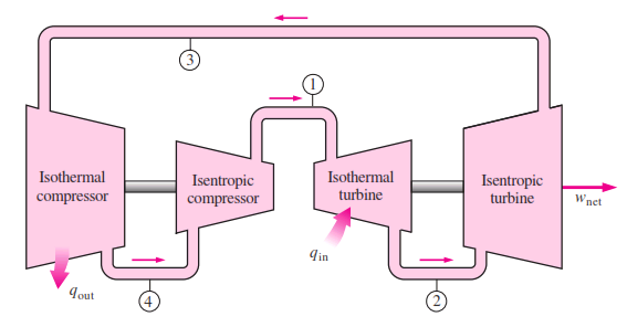
A steady-flow Carnot engine.
AIR STANDARD ASSUMPTIONS
The actual gas power cycles are rather complex. To reduce the analysis to a manageable level, we utilize the following approximations, commonly known as the air-standard assumptions:
1. The working fluid is air, which continuously circulates in a closed loop and always behaves as an ideal gas.
2. All the processes that make up the cycle are internally reversible.
3. The combustion process is replaced by a heat-addition process from an external source
4. The exhaust process is replaced by a heat-rejection process that restores the working fluid to its initial state.
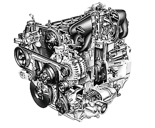
OTTO CYCLE: THE IDEAL CYCLE FOR SPARK IGNITION ENGINES
The Otto cycle is the ideal cycle for spark-ignition reciprocating engines. It is named after Nikolaus A. Otto, who built a successful four-stroke engine in 1876 in Germany using the cycle proposed by Frenchman Beau de Rochas in 1862. In most spark-ignition engines, the piston executes four complete strokes (two mechanical cycles) within the cylinder, and the crankshaft completes two revolutions for each thermodynamic cycle. These engines are called four-stroke internal combustion engines. A schematic of each stroke as well as a P-v diagram for an actual four-stroke spark-ignition
engine is given below :
engine is given below :
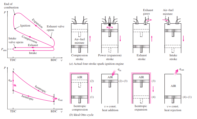
Actual and ideal cycles in spark-ignition engines and their P-v diagrams.
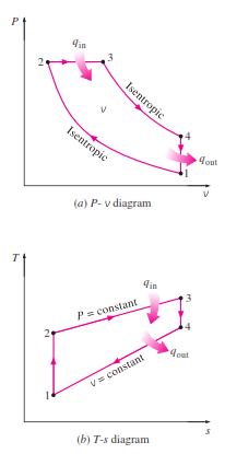
The thermodynamic analysis of the actual four-stroke or two-stroke cycles described is not a simple task. However, the analysis can be simplified significantly if the air-standard assumptions are utilized. The resulting cycle, which closely resembles the actual operating conditions, is the ideal Otto cycle. It consists of four internally reversible processes:
1-2 Isentropic compression
2-3 Constant-volume heat addition
3-4 Isentropic expansion
4-1 Constant-volume heat rejection
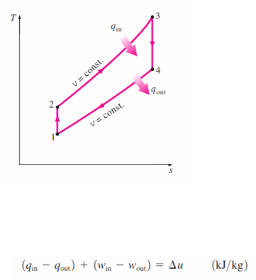
The Otto cycle is executed in a closed system, and disregarding the
changes in kinetic and potential energies, the energy balance for any of the
processes is expressed, on a unit-mass basis, as
1-2 Isentropic compression
2-3 Constant-volume heat addition
3-4 Isentropic expansion
4-1 Constant-volume heat rejection
The Otto cycle is executed in a closed system, and disregarding the
changes in kinetic and potential energies, the energy balance for any of the
processes is expressed, on a unit-mass basis, as
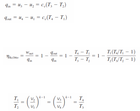
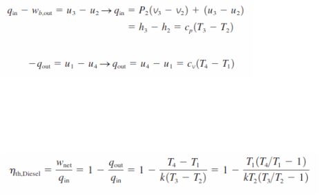
No work is involved during the two heat transfer processes since both take place at constant volume. Therefore, heat transfer to and from the working fluid can be expressed as
Then the thermal efficiency of the ideal Otto cycle under the cold air standard assumptions becomes
Processes 1-2 and 3-4 are isentropic, and v2=v3 and v4=v1. Thus,
Then the thermal efficiency of the ideal Otto cycle under the cold air standard assumptions becomes
Processes 1-2 and 3-4 are isentropic, and v2=v3 and v4=v1. Thus,
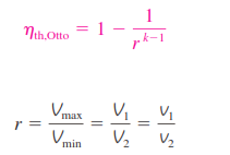
Substituting these equations into the thermal efficiency relation and simplifying gives :
where r is the compression ratio and k is the specific heat ratio cp/cv
The thermal efficiency of the ideal Otto cycle increases with both the compression ratio and the specific heat ratio. This is also true for actual spark-ignition internal combustion engines. A plot of thermal efficiency versus the compression
ratio is shown below for k = 1.4, which is the specific heat ratio value of air at room temperature. For a given compression ratio, the thermal efficiency of an actual spark-ignition engine is less than that of an ideal Otto cycle
because of the irreversibilities, such as friction, and other factors such as incomplete combustion.
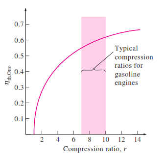
Thermal efficiency of the ideal Otto
cycle as a function of compression
ratio (k =1.4).
DIESEL CYCLE:THE IDEAL CYCLE FOR COMPRESSION-IGNITION ENGINES
The Diesel cycle is the ideal cycle for CI reciprocating engines. The CI engine, first proposed by Rudolph Diesel in the 1890s, is very similar to the SI engine discussed in the last section, differing mainly in the method of initiating combustion. In spark-ignition engines (also known as gasoline engines), the air–fuel mixture is compressed to a temperature that is below the autoignition temperature of the fuel, and the combustion process is initiated
by firing a spark plug. In CI engines (also known as diesel engines), the air is compressed to a temperature that is above the autoignition temperature of the fuel, and combustion starts on contact as the fuel is injected into this hot air. Therefore, the spark plug and carburetor are replaced by a fuel injector in diesel engines.
The P-V and T-S diagram of Diesel Cycle are as follows :
T-s and P-v diagrams for the ideal
Diesel cycle.
Noting that the Diesel cycle is executed in a piston–cylinder device, which forms a closed system, the amount of heat transferred to the working fluid at constant pressure and rejected from it at constant volume can be expressed as
Then the thermal efficiency of the ideal Diesel cycle under the cold-air standard assumptions becomes
Then the thermal efficiency of the ideal Diesel cycle under the cold-air standard assumptions becomes
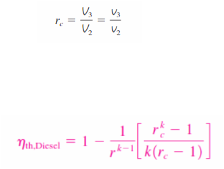
We now define a new quantity, the cutoff ratio rc , as the ratio of the cylinder volumes
after and before the combustion process:
Utilizing this definition and the isentropic ideal-gas relations for processes 1-2 and 3-4, we see that the thermal efficiency relation reduces to
after and before the combustion process:
Utilizing this definition and the isentropic ideal-gas relations for processes 1-2 and 3-4, we see that the thermal efficiency relation reduces to
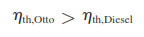
The efficiency of a Diesel cycle differs from the efficiency of an Otto cycle by the quantity in the brackets. This quantity is always greater than 1. Therefore,
when both cycles operate on the same compression ratio.
when both cycles operate on the same compression ratio.
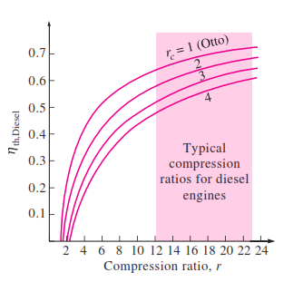
Thermal efficiency of the ideal Diesel
cycle as a function of compression and
cutoff ratios (k =1.4).
BRAYTON CYCLE : THE IDEAL CYCLE FOR GAS TURBINE ENGINES
The Brayton cycle was first proposed by George Brayton for use in the reciprocating oil-burning engine that he developed around 1870. Today, it is used for gas turbines only where both the compression and expansion processes
take place in rotating machinery. Fresh air at ambient conditions is drawn into the compressor, where its temperature and pressure are raised. The high pressure air proceeds into the combustion chamber, where the fuel is burned
at constant pressure. The resulting high-temperature gases then enter the turbine, where they expand to the atmospheric pressure while producing power. The exhaust gases leaving the turbine are thrown out (not recirculated),
causing the cycle to be classified as an open cycle.
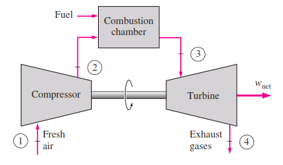
An open-cycle gas-turbine engine.
The open gas-turbine cycle described above can be modeled as a closed cycle, by utilizing the air-standard assumptions. Here the compression and expansion processes remain the same, but the combustion process is replaced by a constant-pressure heat-addition process from an external source, and the exhaust process is replaced by a constant pressure heat-rejection process to the ambient air. The ideal cycle that the working fluid undergoes in this closed loop is the Brayton cycle, which is made up of four internally reversible processes:
1-2 Isentropic compression (in a compressor)
2-3 Constant-pressure heat addition
3-4 Isentropic expansion (in a turbine)
4-1 Constant-pressure heat rejection
1-2 Isentropic compression (in a compressor)
2-3 Constant-pressure heat addition
3-4 Isentropic expansion (in a turbine)
4-1 Constant-pressure heat rejection
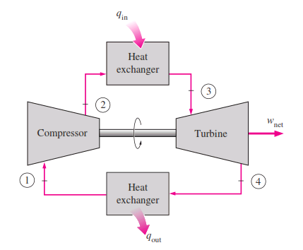
A closed-cycle gas-turbine engine.
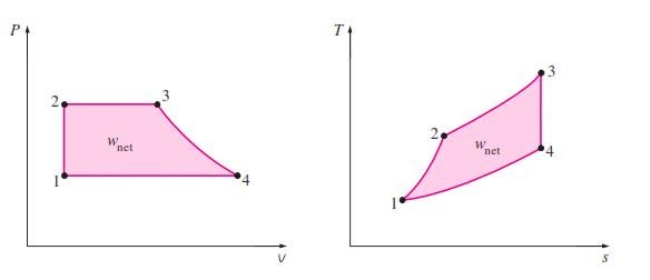
The T-s and P-v diagrams of an ideal Brayton cycle are shown :
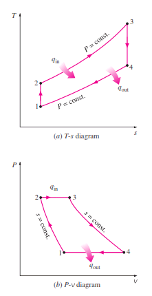
T-s and P-v diagrams for the ideal
Brayton cycle.
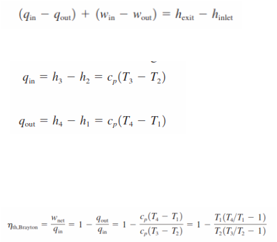
When the changes in kinetic and potential energies are neglected, the energy balance for a steady-flow process can be expressed, on a unit–mass basis, as
Therefore, heat transfers to and from the working fluid are
Then the thermal efficiency of the ideal Brayton cycle under the cold-air- standard assumptions becomes
Therefore, heat transfers to and from the working fluid are
Then the thermal efficiency of the ideal Brayton cycle under the cold-air- standard assumptions becomes
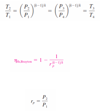
Processes 1-2 and 3-4 are isentropic, and P2 = P3 and P4 = P1 . Thus,
Substituting these equations into the thermal efficiency relation and simplifying give
where,
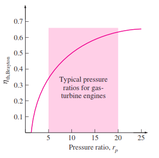
The relation between the efficiency of brayton cycle and the pressure ratio is shown in the diagram below :
Substituting these equations into the thermal efficiency relation and simplifying give
where,
The relation between the efficiency of brayton cycle and the pressure ratio is shown in the diagram below :