
Custom Search
MOHR'S CIRCLE
Mohr's circle, named after Christian Otto Mohr, is a two-dimensional graphical representation of the state of stress at a point. The abscissa, , and ordinate, , of each point on the circle are the normal stress and shear stress components, respectively, acting on a particular cut plane with a unit vector with components . In other words, the circumference of the circle is the locus of points that represent the state of stress on individual planes at all their orientations,where the axes represent the principal axes of the stress element.
Karl Culmann was the first to conceive a graphical representation for stresses while considering longitudinal and vertical stresses in horizontal beams during bending. Mohr's contribution extended the use of this representation for both two- and three-dimensional stresses and developed a failure criterion based on the stress circle.
There is also a similar Mohr's circle for strain where x-axis depicts strain and the y-axis represents half of shear strain which can be found out by Generalised Hooke's Law.
Other graphical methods for the representation of the stress state at a point include the Lame's stress ellipsoid and Cauchy's stress quadric.
MOHR'S CIRCLE FOR TWO-DIMENSIONAL STRESSES
A two-dimensional Mohr's circle can be constructed if we know the normal stresses , , and the shear stress . The following sign conventions are usually used:
- Tensile stresses (positive) are to the right.
- Compressive stresses (negative) are to the left.
- Clockwise shear stresses are plotted upward.
- Counterclockwise shear stresses are plotted downward.
To construct the Mohr circle of stress for a state of plane stress, or plane strain, first we plot two points in the space corresponding to the known stress components on both perpendicular planes, i.e. and (Figure 1 and 2). We then connect points and by a straight line and find the midpoint which corresponds to the intersection of this line with the axis. Finally, we draw a circle with diameter and centre at .
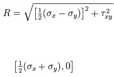
The Radius R of the Circle is
The Coordinates of its centre are as follows:
DRAWING A MOHR'S CIRCLE
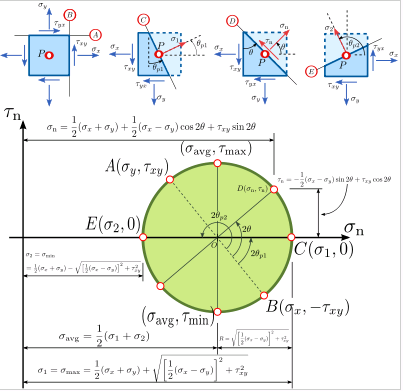
The following procedure is used to draw a Mohr's circle and to find the magnitude and direction of maximum stresses from it.
- First, the - and -axes of a Cartesian coordinate system are identified as the -axis and -axis, respectively.
- Next, two points of the Mohr's circle are plotted. These are the points B (, ) and A (, ). The line connecting these two points is a diameter of the Mohr's circle.
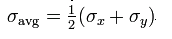
- The center of the Mohr's circle, O, is located where the diameter, AB, intersects the σ-axis. This point gives the average normal stress (σavg). The average normal stress can be read directly from a plot of the Mohr's circle. Alternatively, it can be calculated using
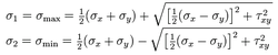
- The Mohr's circle intersects the axis at two points, C and E. The stresses at these two end points of the horizontal diameter are and , the principal stresses. The point represents the maximum normal stress (σmax) and the point is the minimum normal stress (σmin). The equations for finding these values are
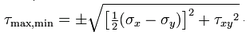
- Next we examine the points where the circle intersects the line parallel to -axis passing through the center of the circle, O. The vertical diameter of the circle passes through O (σavg) and goes up to positive and down to negative . The magnitudes of extreme values are equal to the radius of the Mohr's circle, but with different signs. The equation to find these extreme values of the shear stress is
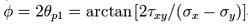
- The next value to determine is the angle that the plane of maximum normal stress makes with the -axis. Let us create a new -axis by drawing a line from the center of the Mohr circle, O, through point A.The angle is found by:
STRESS COMPONENT ON AN ARBITRARY PLANE
Using the Mohr circle one can find the stress components on any other plane with a different orientation that passes through point P. For this, two approaches can be used:
- The first approach relies on the fact that the angle between two planes passing through is half the angle between the lines joining their corresponding stress points on the Mohr circle and the centre of the circle. In other words, the stresses acting on a plane at an angle counterclockwise to the plane on which acts is determined by traveling counterclockwise around the circle from the known stress point a distance subtending an angle at the centre of the circle .
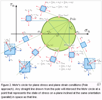
- The second approach involves the determination of a point on the Mohr circle called the pole or the origin of planes. Any straight line drawn from the pole will intersect the Mohr circle at a point that represents the state of stress on a plane inclined at the same orientation (parallel) in space as that line. Therefore, knowing the stress components and on any particular plane, one can draw a line parallel to that plane through the particular coordinates and on the Mohr circle and find the pole as the intersection of such line with the Mohr circle. As an example, let's assume we have a state of stress with stress components , , and , as shown on . First, we can draw a line from point parallel to the plane of action of , or, if we choose otherwise, a line from point parallel to the plane of action of . The intersection of any of these two lines with the Mohr circle is the pole. Once the pole has been determined, to find the state of stress on a plane making an angle with the vertical, or in other words a plane having its normal vector forming an angle with the horizontal plane, then we can draw a line from the pole parallel to that plane . The normal and shear stresses on that plane are then the coordinates of the point of intersection between the line and the Mohr circle.
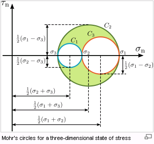
MOHR'S CIRCLE FOR A GENERAL THREE DIMENSIONAL STATE OF STRESS
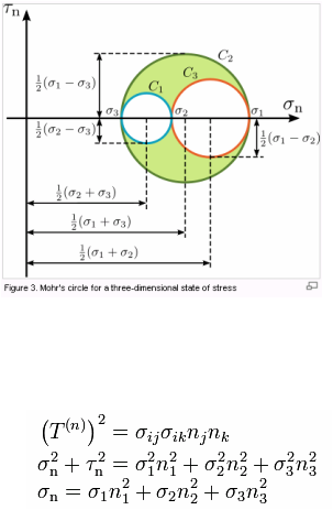
To construct the Mohr's circle for a general three-dimensional case of stresses at a point, the values of the principal stresses and their principal directions must be first evaluated.
Considering the principal axes as the coordinate system, instead of the general , , coordinate system, and assuming that , then the normal and shear components of the stress vector , for a given plane with unit vector , satisfy the following equations
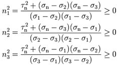
using the Gauss elimination method which yields

Thus the radius of the three circles are as follows
